DR-3
Written by Drenchenator
Last updated on 2008-04-27
Details
| Builder | Drenchentaor |
| Type | Cylindrical CPS |
| Year | 2006 |
| Price | ~100 USD |
| Reservoir Capacity | N/A |
| Chamber Capacity | 1800 mL (60.9 oz) |
| Pump Capacity | 30 mL (1 oz) |
| Shots Per Tank | N/A |
| Pumps Until Full | 30 |
| Dimensions | 24 in. L |
| Weight Empty | 5 lbs |
Performance
| Nozzle | Angled Range | Average Output | Shot Time | Stream Exit Speed |
| 1/16 inch | 38 ft | 1.52 oz/s | 40 s | 22.7 m/s |
| 11.58 m | 45 mL/s | |||
| 5/8 inch | 15 ft | 40.6 oz/s | 1.5 s | 6.1 m/s |
| 4.57 m | 1200 mL/s |
Overview
I attempted to build this gun for a variety of reasons, the most important being the overall lack of aesthetics or looks in homemade water guns. I wanted to build one that was essentially a copy of the CPS 3000 or 3200: a large bladder fed from a pump connected to a backpack. The gun accomplished that to a certain degree.
I'm from this point going to refer to this are DR-3, which may seem odd but actually makes a lot of sense to me. You see, my handles on NerfHaven, SSCentral, and iSoaker.net all start with the letters D and R—Dr. Nerf, Drenchenator, and Drenchenator again. This was my third homemade air or water gun, so I added the 3 to designate this. I did have a real name, a creative name, when I was building DR-3, but I feel that that name would be best suited for a completed project.
The pieces of paper below the parts layout in some of the pictures were made in MacDraw from 1985. It's amazing what 20 year old software can do sometimes; it saved me a ton of time getting the dimensions to work out.
Firsts
This gun had several firsts for a homemade water gun:- Wire trigger system - I just copied the standard in stock guns. It was an obvious choice.
- Trigger - If I remember correctly, this gun was the first to really succesfully implement a trigger to open the valve; closing was a different story.
- Internals - This is the only homemade gun that I know of that has true internals—the inner workings of the gun are hidden from the user.
Design
Initial Idea
This design was the culmination of many ideas and my experiences building Nerf guns. In late September 2005, I came up with an idea for a duplicate of the classic SS 100. I made a drawing but later dismissed it because the valve that I was going to make would not seal well. The idea struck me again in June 2006, but this time, I wanted to create a copy of the SS 50. I made another simple drawing and later made a diagram. My copy would have used a "double pinch" valve, based on the original cheap classic soaker valves (they leaked horribly). I actually went out to Lowes to buy the parts to make this gun, but at store I noticed that the valve and soaker would probably not be worth the price that I would pay for them. The results would have been more that likely weak for a homemade soaker, so I began to seek more power.
Using my homemade valve making experience, I quickly thought of a simple copy of the standard Super Soaker pull valve using rubber sheeting and piping. I bought a 2" cross to build my test valve out of for my new gun. When I got home later, I noticed how huge this valve would be. So I minimized it and designed a smaller valve made out of a 1/2" cross.
This simple pull valve intrigued me. Ben had some extra latex rubber tubing, so I settled on building a homemade CPS gun. I came up with a design (above), and went to Lowes again to buy the rest of the parts for it. Some unusual parts were found (most notable the swing check valve to save space) and implemented in the design. This design was considered "finalized" by early July and I began construction of it. Some major design features that were kept from this design include the 60 mL pump, pump shaft tracked trigger, swing check valves, and massive pressure chamber (as well as the use of 1 1/2" PVC for the body). The length of this gun design was 27 inches and the design was a step in the right direction.
However, early on I began to doubt this guns performance and ability to be built. I thought that it would really not be worth to build if it used a pull valve, which really is not optimal for performance. A pull valve creates a lot of turbulence, so I then began to think of a way to modify a ball valve to use the trigger system that I came up with. I also wanted to make the gun smaller at the same time while maintaining the capacity.
Redesigns
There were flaws in the original design, which led me to redesign the gun. Many of the features, such as the pump, were overly complicated to build and wasteful of parts and space. Just to lead to the check valve, I created a huge U in the piping just so that the check valve is oriented vertically instead of horizontally. The pull valve was another major issue. Though its operation was simple, it would restrict the flow and create a lot of turbulence with its two 90 degree bends. These problems were solved by simplifying the their function. Last but not least, the gun would have been very tall (over 7 inches not counting the handle I believe), which is not the zenith of ergonomics.
The pump was redesigned to only take up space in one pipe by just putting the check valve where any other person would have, behind the pump shaft. The trigger valve was also simplified into a tee with a ball valve to maximize the laminar flow. Galvanized steel pipe fittings were chosen for the valve because they were fairly cheap and because every end was threaded. This saved space, which in turn allowed the gun to go from 3 layers of 1.5 inch pipe, to 2 layers, greatly reducing the height and size. The size reduction also chopped off three inches in length, making the new design only 24 inches (two feet) long.
Changes During Construction
Early on in construction, the steel elbow was replaced with a PVC equivalent. This was to allow the wire to travel from the valve to the trigger system more easily. Though the elbow was would have worked well there, I wanted to optimize for internal space.
At this point I was able to build the gun in the pictures. A few things slowed me down though. The first major problem was trigger system in general. There was some friction between the parts that I got rid of soon enough. But the torque arm and wire connection to it lingered as problems. The first two torque arm designs failed, but the third worked. But I couldn't get the valve to open all the way. Despite how much I tugged on the trigger, it wouldn't open all the way; it would only open about three quarters the way. The problem was simple: Not enough force was getting to the torque arm in the direction of motion. Ideally, the wire should be perpendicular to the arm pulling the direction you want it to go, where the magnitude of the cross product would be maximized. I didn't do that originally. The fix was simply making the arm pull backwards parallel to the direction of motion right at and around the connection point. This provided enough tension to pull the valve completely open.
By the time I solved this problem another problem arose: closing the valve. It's one thing to open it; it's another to get it to close, like how real soakers, stock soakers do it. My original plan was just to mount a spring and hope for the best—and it obviously didn't work. I couldn't close the valve no matter what I used and did: I tried springs; I tried rubber bands; and I even tried both at the same time. Nothing. I wouldn't close. In retrospect, I believe this is just from the utter lack of torque I used; I just connected it and hoped for the best. I should have designed for this. I knew how to; I just didn't. I just thought it would work. As a tip for builders, always calculate everything you can; you'll save yourself the hassle that I went through. I believe the true way to solve this problem, though, would be to build a special arm around the valve much like the ones used in the Flash Flood and Arctic Blast with the spring-loaded closing arms. Just an idea that I saw before.
I struggled to solve that problem—and never did—so I didn't complete the gun. Summer ended; school started; I forgot about it and let it be. I went back to it in the summer of 2007 to attach the handle as seen below, but I never truly finished it.
Current Status
I've stopped working on this gun. In all, I learned a lot from it, but I believe right now that I was getting nowhere with it. Perhaps one day I will complete it and declare it completely functional, but as of right now it doesn't look like that's gonna happen. Hopefully what I've outlined here will help future builders avoid the same pitfalls I fell into and build some rather exceptional homemade water guns. Good luck.
Photos
The Internals and Finished Parts
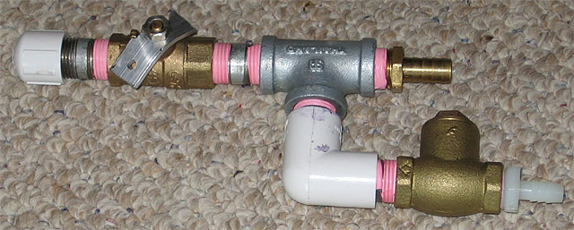
The entire gun disassembled. The gun was more like a stock soaker than any other one, but it still couldn't just have old half of the casing removed to see the internals. To do that you would have to take apart the whole gun as shown above.
The vinyl tube connecting the pump to the second swing check valve.
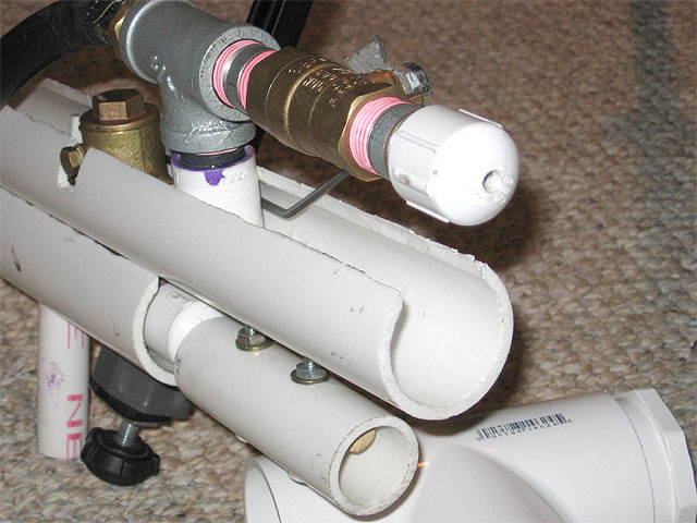
The bolts that connect the bottom and middle tubes together. The pipe they connect to is screwed on the bottom of the bottom pipe. This way the pump can fit within the 1" pipe and the gun can still be held together.
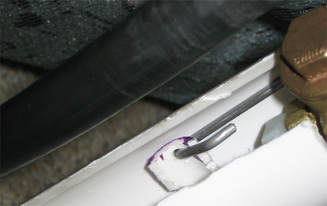
The trigger connection point next to the second swing check valve.
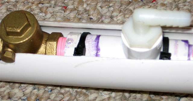
The pump connection and first swing check valve in the bottom tube.
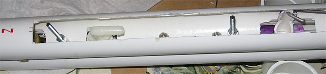
The second tube, showing the pump connection, bolts to connect the chamber casing, and the trigger-wire connection.
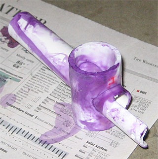
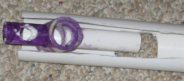
The trigger itself was an interesting part. It the pump had to go through it to guide it. I did this by cementing a 1/2" pipe through a 1" pipe and drilling out the center. Once sanded, it presented no problems and was one of the few things that worked at the first try.
I kept the trigger valve and one of the check valves in a a single unit. This differed from the convention in most stock soakers—they keep both check valves as close to the pump as possible. This was the only way I could fit both on them into the pipes.
I had to wedge the trigger into the pipe to get it to fit.
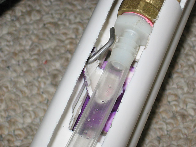
Another shot of the trigger and vinyl tube barb.
The nozzle.
The Almost Finished Product
Shot Images
Successes and Failures
The Good
- Small size - The gun was a grand total of 24 inches long, much smaller than any other homemade up to that point. The 1 1/2" PVC pipe offered just enough room for the parts to fit.
- Functionality - The gun shot water 38 feet at about 1 oz/sec during testing. It also managed a 40 oz/sec riot blast.
- Handle - Later—much later in fact—I added a handle which worked excellently with the overall design.
- "Stacked pipe" design - The casing for the gun just three PVC pipes. This worked well: The pump took up the bottom pipe; a myriad of other internals in the second; the top with the bladder and firing valve.
- Vinyl tubing - Clear 3/8" vinyl tubing saved the project. Without it, I would've used rigid PVC pipe, making the gun a lot larger. The tubing worked with the screws well too.
- Pump - The pump that I built was amazing. Not only did the handle work out well, but the pump itself was worked excellently due to a little elbow grease and well... actual grease.
The Bad
- Screw placement - My original idea was that this would just come together and I could put the screws pretty much anywhere. That wasn't the case—the screws couldn't go through the internals, creating a major problem with a slick solution on my part. I just put screws around the internals through a small 1" PVC in the same pipe as the pump. This held together the gun well but left the ends of screws sticking out of the gun right next to where the handle would go.
- Weight - The gun, though small, weighed several pounds empty. This was a combination of factors: For one the gun was densely paced with internals; plus the metal parts didn't seem to help.
The Ugly
- Swing check valves - Looking to save some space, I selected swing check valves instead of spring check valves. Swing check valves are taller than spring check valves, but are shorter. They also don't open or close at certain angle because they work with gravity. The valves were very heavy—made from brass in fact—and added too much weight to the system as a whole. The holes I had to make to accomodate them also didn't make building the gun any easier.
- Trigger system - The trigger itself worked excellently; but that wasn't the problem with the overal valve opening system. Originally, the valve opened but not all the way. I corrected this by redoing the trigger wire several times to maximize the force used to open the valve (the wire must pull in the direction of motion). However, this was just half of the problem: I couldn't get the valve to close. The spring I chose to close the valve couldn't do it. I should've designed the system better.
Planned Materials List
| Part (length in parenthesis) | Quantity | Price | Planned Use |
| Schedule 40 1/2" PVC Pipe (5') | 1 | $2 | Pump Shaft, Trigger Assembly |
| Schedule 40 1" PVC Pipe (5') | 1 | Grip, Pump Handle, Internals | |
| Schedule 40 1 1/2" PVC Pipe (5') | 1 | $5 | Body |
| 4" Drainage PVC Pipe (5') | 1 | $7 | Top Layer (Bladder) Casing |
| 1/2" CPVC Pipe (5') | 1 | O-ring Mounts | |
| 1/2" Schedule 80 PVC Pipe Nipple (12") | 1 | Part of Trigger Valve | |
| 1/2" Schedule 40 PVC Tee with Femaled Threaded Top | 1 | $0.50 | Part of Pump Shaft |
| 1/2" Schedule 40 PVC Unthreaded End Cap | 1 | $0.50 | Pump Cap |
| 1/2" Schedule 40 PVC Threaded End Cap | 3 | $1.50 ($0.50 each) | Nozzle |
| 1/2" Schedule 40 PVC Male Adapter | 1 | $0.25 | Part of Pump Shaft |
| 1/2" Schedule 40 PVC 90° Elbow Female Adapter | 1 | $0.50 | Part of Trigger Valve |
| 1/2" Galvanized Steel Pipe Nipple (1 1/8" length) | 1 | $1 | Part of Trigger Valve |
| 1/2" Galvanized Steel Pipe Nipple (1 1/2" length) | 2 | $2 ($1 each) | Part of Trigger Valve |
| 1/2" Galvanized Steel Pipe Tee | 1 | $1 | Connection between the Bladder and Valve |
| 3/8" x 1/2" Nylon Hose Barb | 2 | $3 (1.50 each) | Connect Pump to Trigger Valve and Reservior |
| 3/8" x 1/2" Nylon 90° Elbow Hose Barb | 1 | $1.50 | Connect Pump to Trigger Valve |
| 1/2" x 1/2" Brass Hose Barb | 1 | $2 | Bladder Connection |
| 1/2" Brass Female Threaded Ball Valve | 1 | $6 | Trigger Valve |
| 1/2" Brass Female Threaded Swing Check Valve | 2 | $13 ($6.50 each) | Prevent Backflow in Pump and Trigger Valve |
| 1/8" x 3/4" x 3' Aluminum Sheeting | 1 | $4 | Trigger Valve Torque Arm |
| Latex Rubber Tubing (8") | 1 | Pressure Chamber | |
| 1/2" OD 3/8" ID Vinyl Tubing (9") | 1 | Connection between Pump and Chamber | |
| 1/2" Wooden Dowel (2') | 1 | Pump Rod | |
| 1/2" ID 5/8" OD O-ring | 3 | Seal in Pump | |
| Thread Seal Tape | 1 | $2 | Seal All Threaded Connections |
| PVC Cement | 1 | Cement Together the Pump Shaft and Trigger Valve | |
| PVC Primer | 1 | Clean the Pump Shaft and Trigger Valve Before Cementing | |
| Zip Ties | 2 | Hold the Pump Shaft Down | |
| Nuts, Bolts, Spacers and Washers | Hold the Externals Together | ||
| Rigid Iron Wire | Connect the Trigger Valve to Trigger | ||
| Hot Stuff (glue) | Glue for the Pump Rod | ||
| Epoxy | Other Glue | ||
| Wood | Other Stuff | ||
| Total Cost | $70 to $100 | To soak people |
Tools Used
- Safety Glasses or Goggles
- Dust Mask or Respirator*
- Gloves*
- Adjustable Wrench
- Slot-head Screwdriver
- Saw (for PVC and wood)
- Hack Saw (for metal only)
- Miter Box and Saw
- Dremel Tool
- Variable Speed Dremel
- Sandpaper
- File
- Vice
- Scissors
- Clear Tape (as a tool)
- Pencils and Pens
- Eraser (for cleaning the pipe too)
- Pipe Wrench (for steel pipe)
- Drill
- Drill Press
- 7/8" Hole Saw
- 3/16" Drill Bit
- Reamer